Wireless Communication Protocols and Mobile Network Architecture
Wireless Application Protocol (WAP) Fundamentals
WAP (Wireless Application Protocol) is a set of protocols designed for wireless devices (like mobile phones and PDAs) to access internet services. It uses a client-server model, with the mobile device acting as the client and a WAP gateway/web server as the server. WAP optimizes content for low bandwidth, small screens, and limited processing power.
WAP Protocol Stack Layers
The WAP model is structured into several distinct layers:
- Application Layer: Includes the Wireless Application Environment (WAE), mobile device specifications, and content languages like WML.
- Session Layer: Contains the Wireless Session Protocol (WSP) for fast connection suspension and reconnection.
- Transaction Layer: Includes the Wireless Transaction Protocol (WTP) on top of UDP, supporting reliable transactions.
- Security Layer: Contains Wireless Transport Layer Security (WTLS) for data integrity, privacy, and authentication.
- Transport Layer: Contains Wireless Datagram Protocol (WDP), ensuring a consistent data format for higher layers.
Key WAP Protocols
- WTP (Wireless Transaction Protocol): Handles transactions.
- WSP (Wireless Session Protocol): Manages sessions.
- WML (Wireless Markup Language): Markup language optimized for small screens.
- WMLScript (Wireless Markup Language Script): Scripting language used for dynamic content.
- WAE (Wireless Application Environment): Defines WAP’s application architecture.
WAP 1.0: Advantages and Disadvantages
Advantages of WAP 1.0
- Optimized for small screens and low bandwidth.
- Reduced data usage.
- Unified platform for mobile applications.
Disadvantages of WAP 1.0
- Limited content and poor user experience on early devices.
- Obsolete with newer technologies and faster networks.
WAP 1.0 Architecture and Communication
WAP 1.0 was a groundbreaking development in mobile computing. It provided a standardized way for mobile devices to access content from the web, defining a specific architecture to facilitate this interaction while considering mobile constraints like small screens, low processing power, and limited bandwidth.
Key Components of WAP 1.0 Architecture
- WAP Client (Mobile Device/WAP Browser): A mobile device with a WAP browser that uses WML (Wireless Markup Language) for optimized display on small screens.
- WAP Gateway (Proxy Server): Acts as an intermediary to convert HTTP requests into WSP (Wireless Session Protocol) and compress data to save bandwidth.
- WAP Server: Serves WML content and WMLScript for interactive features, specifically designed for mobile devices.
- WAP Protocol Stack:
- WDP (Wireless Datagram Protocol): Transport layer for reliable datagram services.
- WSP (Wireless Session Protocol): Session management and communication between client and gateway.
- WTP (Wireless Transaction Protocol): Ensures reliable transaction communication.
- WML: Lightweight markup language for mobile devices.
- WMLScript: Scripting for interactivity on mobile devices.
- Wireless Transport Network: The mobile network (e.g., GSM, CDMA) connecting the device to the gateway, often characterized by low data speeds (9.6 to 14.4 kbps).
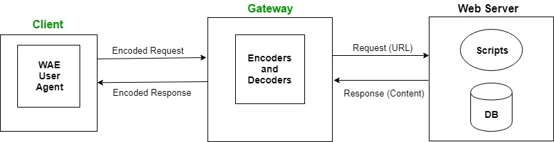
WAP 1.0 Communication Flow
- User Request: The mobile device sends a WSP request to the WAP Gateway.
- Protocol Conversion: The Gateway converts the request into HTTP for the web server.
- Content Delivery: The WAP Server sends back WML content, which the Gateway compresses.
- Data Display: The WAP client decompresses and displays the content on the mobile device.
WAP 1.0 Advantages and Limitations
Advantages
- Low Bandwidth Usage: Optimized for mobile networks with limited data.
- Simplified Content: WML is easier to display on small screens than full HTML.
- Mobile Interactivity: WMLScript enables dynamic user interactions.
- Standardized Protocols: Ensures interoperability across devices and networks.
Limitations
- Limited Multimedia: Primarily supports text and simple images.
- Slow Speeds: Early mobile networks were slow, impacting browsing speed.
- Basic UI: WAP browsers offered a minimal user experience compared to modern apps.
- Incomplete Internet Experience: Many standard web features were not supported.
 WAP Protocol
 Architecture
Mobile IP: Seamless Mobility in Networks
Mobile IP is a communication protocol in mobile computing that allows mobile devices (like smartphones, laptops, etc.) to maintain a continuous internet connection while moving between different networks. It enables seamless communication as a mobile device changes its point of attachment to the internet without losing the connection or requiring the user to re-establish it.
Key Components of Mobile IP
- Mobile Node (MN): The device (e.g., smartphone) that moves across networks, maintaining a permanent Home IP address.
- Home Network: The original network where the mobile device is registered, including the Home Agent and home server.
- Foreign Network: Any network the mobile device connects to while traveling, assigning it a temporary Care-of Address (CoA).
- Home Agent (HA): A router in the Home Network that tracks the mobile device’s location and forwards packets to its Care-of Address.
- Foreign Agent (FA): A router in the Foreign Network providing the temporary Care-of Address and forwarding packets to the device.
- Care-of Address (CoA): A temporary address used to route packets to the mobile device while in a foreign network.
Mobile IP Communication Process
- Device Moves to Foreign Network: The Mobile Node obtains a Care-of Address (CoA).
- Registration with Home Agent: The mobile device informs the Home Agent of its new location (CoA).
- Packet Forwarding: The Home Agent forwards data to the mobile device’s Care-of Address via tunneling.
- Decapsulation and Delivery: The Foreign Agent (or the device itself) decapsulates and delivers the data.
- Continued Communication: The mobile device maintains communication via its permanent Home IP.
- Movement Detection: The device updates the Home Agent with a new CoA when moving again.
Mobile IP Benefits and Limitations
Benefits
- Seamless Mobility: Continuous communication across networks.
- No IP Change: Device keeps its Home IP address.
- Transparent to Applications: Works at the network layer, not requiring application changes.
- Supports Multi-Networks: Device switches networks without IP reconfiguration.
Limitations
- Latency & Overhead: Increased latency due to tunneling.
- Scalability: The Home Agent may become a bottleneck with many devices.
- Security Risks: Vulnerabilities exist in registration message authentication.
- Handover Delays: Potential delays during network handovers.

Multiple Access Techniques: CDMA vs. SDMA
| Feature | CDMA (Code Division Multiple Access) | SDMA (Space Division Multiple Access) |
|---|---|---|
| Access Method | Uses unique codes to differentiate users in the same frequency band. | Uses spatial separation to differentiate users (e.g., multiple antennas or sectors). |
| Frequency Usage | All users share the same frequency spectrum, but each has a unique code. | Users are allocated different spatial channels based on their physical locations. |
| Interference | Users can interfere with each other if codes are not properly assigned (near-far problem). | Minimal interference if spatial separation is managed well. |
| Capacity | Can support many users in the same frequency band, but capacity is limited by code availability. | Capacity depends on the number of spatial channels (e.g., antenna arrays). |
| Efficiency | Highly efficient for dense networks due to code reuse. | Efficiency depends on the quality of spatial separation and antenna configurations. |
| Applications | Primarily used in cellular networks (e.g., CDMA2000, WCDMA). | Used in satellite communications, cellular base station antenna systems, and MIMO systems. |
| Complexity | Requires complex encoding and decoding processes. | Requires sophisticated antenna systems and signal processing. |
| Advantages | High spectral efficiency, better for long-range communication. | Reduces interference by leveraging physical space separation. |
| Disadvantages | Requires more power and complex management of codes. | Limited by physical infrastructure and may not be as efficient in dense urban areas. |
Cellular Wireless Network Architecture
A Cellular Wireless Network is the backbone of mobile computing in most modern communication systems. It refers to a network infrastructure that divides geographic areas into “cells,” each served by a base station that provides wireless communication services (voice, data, and more) to mobile devices within that cell. Cellular wireless networks enable mobile devices, like smartphones and tablets, to stay connected while users move around and roam between cells without dropping calls or losing internet connectivity.
Key Features of Cellular Networks
Cellular Architecture:
- Cells: Geographic areas served by base stations, enabling coverage and communication.
- Base Station: Connects devices to the network.
- Mobile Switching Center (MSC): Routes calls, messages, and data.
- Handover: Seamless transfer of calls/data between cells as the device moves.
Frequency Reuse: The same frequencies are reused in different cells, enhancing spectrum efficiency and network capacity.
Communication Types:
- Voice: Circuit-switched for voice services.
- Data: Packet-switched for internet, apps, and downloads.
- Text (SMS) and Multimedia (MMS): Sending texts and multimedia content.
Generations of Cellular Networks:
- 1G: Analog voice.
- 2G: Digital voice/text (GSM, CDMA).
- 3G: Broadband mobile internet (UMTS, CDMA2000).
- 4G: High-speed internet (LTE, WiMAX).
- 5G: Ultra-fast speeds, low latency, supports IoT and VR.
Multiple Access Techniques: FDMA, TDMA, CDMA, and OFDMA (used in 4G/5G) allow multiple users to share the same spectrum.
Backhaul & Core Network:
- Backhaul: Connection between base stations and the core network.
- Core Network: Routes data and handles communication between regions.
Data Services & QoS: Modern networks offer Quality of Service (QoS) for reliable, high-performance applications like video calls and gaming.
Security: Authentication, Encryption, Location Privacy, and Integrity Checks protect data and users.
Challenges: Capacity, Coverage, Interference, Handover Delays, and Battery Life are key issues to manage.
Key Technologies: Wi-Fi Offloading, MIMO, Small Cells, and Carrier Aggregation enhance mobile network performance and coverage.
Cellular Network Advantages and Disadvantages
| Advantages | Disadvantages |
|---|---|
| Supports both mobile and fixed users. | Provides lower data rates compared to wired networks (e.g., fiber optics, DSL). |
| Offers voice and data services. | Data rate varies based on wireless technology (GSM, CDMA, LTE). |
| Increased capacity and easy to maintain. | Multipath signal loss affects reception quality. |
| Easy to upgrade equipment and consumes less power. | Limited capacity based on channels and access techniques. |
| Wireless nature allows use where cables can’t be laid. | Security issues due to the wireless connection. |
| Can support large coverage areas. | Requires time and labor for antenna tower construction. |
Wireless Local Area Networks (WLAN)
WLAN stands for Wireless Local Area Network. A WLAN uses radio communication to provide mobility to network users while maintaining connectivity to the wired network. A WLAN essentially extends a wired local area network. WLANs are built by attaching an Access Point (AP) to the edge of the wired network. Clients communicate with the AP using a wireless network adapter. It is also known as a LAWN (Local Area Wireless Network).
WLAN Authentication and Association
Authentication: Ensures the Station (STA) is authorized to join the network, typically using Open System or Shared Key Authentication.
Association: The STA establishes a connection with the AP to send/receive data after successful authentication.
IEEE 802.11 Protocol Stack and Components
The IEEE 802.11 standard defines the architecture for WLANs:
- Mobile Devices (STAs): Devices (laptops, smartphones, tablets) that connect to the network, each with a unique MAC address.
- Access Point (AP): Central device that connects STAs to the network, acting as a bridge between the wireless and wired network.
- Basic Service Set (BSS): A network with a single AP and its associated STAs. This can be infrastructure mode (with AP) or ad-hoc mode (no AP).
- Extended Service Set (ESS): Multiple BSSs connected to allow seamless roaming across a larger area.
- Distribution System (DS): A backbone connecting multiple BSSs in an ESS, enabling communication across different APs.
- Authentication Server (RADIUS): Used for authenticating STAs, providing security through AAA protocols.
Protocol Layers
- Physical Layer (PHY): Responsible for data transmission over the airwaves (e.g., 2.4 GHz, 5 GHz). Different standards (802.11a, b, g, n, ac, ax) vary in speed and range.
- Data Link Layer (MAC and LLC):
- MAC: Manages access to the wireless medium using CSMA/CA (Carrier Sense Multiple Access with Collision Avoidance).
- LLC: Handles error checking, flow control, and communication with higher layers.
Security and Encryption
Security protocols like WEP (outdated), WPA/WPA2, and WPA3 provide encryption and security to ensure data privacy.
Communication Models
- Infrastructure Mode: STAs communicate via an AP, commonly used in Wi-Fi networks.
- Ad-Hoc Mode: STAs communicate directly without an AP, useful for temporary networks.
WLAN Advantages and Disadvantages
| Advantages | Disadvantages |
|---|---|
| Flexibility in device placement and movement. | Weak signal areas (dead zones) limit mobility. |
| Quick and easy to set up with fewer cables. | Complex setup for large networks, requires access points. |
| Lower installation cost where wiring exists. | May need expensive equipment (APs, routers). |
| Easy to add devices without extra cables. | Performance may degrade with growth unless well managed. |
| Access network from various locations. | Interference from other wireless devices. |
| High speeds with modern standards (Wi-Fi 5, 6). | Slower than wired networks, especially with older standards. |
| Extendable with additional access points. | Limited by obstacles and interference. |
| Strong encryption (WPA2, WPA3). | More vulnerable to security risks if not properly secured. |
| Low interference in ideal conditions. | Susceptible to interference from other devices (Bluetooth, etc.). |
| Minimal physical maintenance. | Needs monitoring for performance and interference. |
| Improved with newer tech (Wi-Fi 6, MU-MIMO). | Reliability drops with more users or congestion. |
| Conserves power in mobile devices. | Higher energy use compared to wired networks. |
| Works with most modern devices. | Older devices may not support newer WLAN standards. |
WAP 2.0: Evolution of Mobile Web Access
WAP 2.0 was designed to work on more modern mobile networks, taking advantage of higher bandwidth and the full power of contemporary mobile devices. The most notable difference between WAP 1.0 and WAP 2.0 is that WAP 2.0 supports XHTML (Extensible Hypertext Markup Language), an upgraded version of HTML, rather than the old WML used in WAP 1.0. This allows for a much richer mobile web browsing experience.
Key Components of WAP 2.0 Architecture
Mobile Device (WAP Client): Devices (phones, tablets) with WAP 2.0 browsers capable of rendering XHTML, CSS, and JavaScript, connecting via GPRS, EDGE, UMTS, LTE, or Wi-Fi.
WAP Gateway: Intermediary between the mobile device and the internet, converting HTTP to WSP and compressing data for optimized transfer.
WAP Server: Hosts content (XHTML, multimedia) for mobile devices, supporting modern web formats for richer user experiences.
Content Provider: Source of optimized content for mobile devices, adapting to various network speeds.
WAP 2.0 Protocol Stack
Wireless Transport Layer (WTP): Ensures reliable, transaction-oriented communication, handling data integrity.
Wireless Session Layer (WSP): Manages session persistence and data flow between mobile devices and servers, optimized for wireless.
Wireless Transport Layer Security (WTLS): Provides encryption, ensuring data integrity and secure communication.
Application Layer (XHTML, CSS, JavaScript): Supports modern web technologies for rich mobile web experiences.
Content Adaptation Layer: Optimizes content based on device capabilities (e.g., screen size, bandwidth).
Communication Flow of WAP 2.0
User Request: Mobile device sends a URL or link request to the WAP Gateway.
WAP Gateway Communication: Converts, compresses, and forwards the request to the WAP Server.
Content Retrieval & Optimization: WAP Server retrieves and sends optimized content back through the Gateway.
Response Display: Mobile device receives and displays content, processing interactive elements.
Key Features of WAP 2.0
XHTML Support: More compatible with standard web pages.
Improved User Experience: CSS and JavaScript support for richer, interactive content.
Faster Data Transfer: Compression and optimized session management.
Security: WTLS ensures encrypted and secure data transmission.
Content Adaptation: Optimizes content based on device capabilities.
Advantages of WAP 2.0 over WAP 1.0
Enhanced Compatibility: Provides an experience closer to desktop browsing.
Better Performance: Improved data transfer and lower latency.
Richer Experience: Support for complex websites and interactive content.
Security: End-to-end encryption via WTLS for safer mobile transactions.
Comparison of Multiplexing Techniques (FDM, TDM, CDM)
| Feature | FDM (Frequency Division Multiplexing) | TDM (Time Division Multiplexing) | CDM (Code Division Multiplexing) |
|---|---|---|---|
| Single transmission | Simultaneous, different frequencies | Sequential, different time slots | Simultaneous, different codes |
| Bandwidth Requirement | High bandwidth for multiple frequencies | Lower bandwidth, shared frequency | Efficient, supports more users |
| Synchronization | None required | Requires precise time synchronization | Requires synchronization of codes |
| Complexity | Low | Moderate, time slot management | High, encoding/decoding complexity |
| Efficiency | Less efficient if not fully utilized | More efficient with limited bandwidth | Very efficient, supports many users |
| Interference Risk | High if frequencies overlap | Low, but still possible in congestion | High if codes overlap |
| Use Cases | Radio, TV, analog communications | Telephone systems, digital circuits | Cellular networks, GPS, satellites |
| Resource Allocation | Frequency division | Time division | Code division |
| Capacity | Limited by frequency bands | Limited by time slots | High, many users in same band |
| Latency | Low (constant availability) | Depends on time slot duration | Higher due to processing overhead |
GSM Call Routing and Core Network Components
Call Routing in GSM (Global System for Mobile Communications) refers to the process of directing a call from one mobile device to another, whether it’s within the same network or across different networks. This process involves several key components and steps, including the mobile network’s core infrastructure and signaling systems.
Key Components in GSM Call Routing
| Component | Function |
|---|---|
| Mobile Station (MS) | The mobile device making or receiving the call. |
| Base Station (BS/BTS) | Connects the MS to the network, handling radio communication. |
| Base Station Controller (BSC) | Manages multiple BTSs and handles call handovers. |
| Mobile Switching Center (MSC) | Central node for call setup, routing, and resource management. |
| Visitor Location Register (VLR) | Temporary storage of subscriber information in a given MSC area. |
| Home Location Register (HLR) | Permanent database of subscriber information and service details. |
| Gateway MSC (GMSC) | Routes calls between GSM and external networks (PSTN, other GSM networks). |
| Short Message Service Center (SMSC) | Handles SMS message routing. |
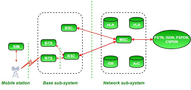
Call Routing Process (Mobile-to-Mobile)
- Call Initiation: Mobile A sends a setup request to the nearest BTS, which forwards it to the BSC and MSC.
- Location Tracking: The MSC queries the VLR for Mobile B’s location. If unknown, it checks the HLR for the correct VLR.
- Call Routing: The MSC sets up a path from Mobile A to Mobile B via the BTS, BSC, and the core network.
- Call Establishment: Mobile B answers; a full connection is established, allowing voice transmission.
- Call Termination: Either party ends the call, and the MSC releases resources.
- Call Completion (Billing): The MSC sends billing data to the HLR to record call details.
Call Routing in Other Scenarios
Mobile-to-Landline: Routed through the GMSC to the PSTN (Public Switched Telephone Network).
Inter-network Call: Routed via the GMSC and interconnect points between different networks.
Roaming Call: The HLR redirects the call to the VLR/MSC in the visited network.
GSM Security Services and Mechanisms
GSM (Global System for Mobile Communications) is a standard for mobile telephony that supports digital cellular networks. Since mobile communication involves the transmission of sensitive data (such as voice calls, text messages, and user information), security plays a critical role in ensuring privacy and protecting the network and users. GSM has several built-in security services implemented using encryption techniques, user authentication, and other mechanisms. The key security services in GSM are Authentication, Encryption, Integrity of messages, and Confidentiality.
Key Security Services in GSM
Authentication
Purpose: Verifies the user’s identity.
Process: Uses the International Mobile Subscriber Identity (IMSI) from the SIM card. A challenge-response mechanism with a secret key (K) stored on the SIM is used to authenticate the device.
Encryption
Purpose: Ensures the privacy of communications by encrypting voice and data.
Process: A session key, generated during authentication, encrypts communications using algorithms like A5/1 or A5/2.
Integrity Protection
Purpose: Ensures that transmitted data hasn’t been tampered with.
Process: Uses checksums and hash functions to verify data integrity.
Confidentiality
Purpose: Prevents unauthorized access to user data.
Process: Encryption of voice and data using session keys ensures that only authorized parties can access the communication.
GSM Security Mechanisms
Authentication
SIM Card Authentication: Challenge-response using the secret key (K) stored on the SIM.
A3/A8 Algorithms: A3 generates the response; A8 generates the encryption key for communication.
Encryption
A5 Algorithms:
A5/1: Strong encryption, mainly used in Europe and North America.
A5/2: Weaker encryption, used in some regions.
A5/3: Introduced for stronger encryption in GSM Phase 2.
Session Key: Derived from the SIM secret key and RAND value, used for encrypting voice and data transmissions.
