Digital Logic Circuits: Flip-Flops, Registers, Counters & Parameters
Advantages of Edge-Triggered RS Flip-Flops
The primary advantage of an edge-triggered RS flip-flop over a clocked or gated RS flip-flop lies in its ability to respond to changes in input only at specific moments, typically on the rising or falling edge of a clock signal. Here are some key advantages:
- Reduced Glitches: Edge-triggered flip-flops only sample the input signals at the moment of the clock edge, which minimizes the risk of glitches that can occur in gated flip-flops when inputs change while the clock is high.
- Improved Timing Control: Edge-triggered flip-flops provide better timing control in synchronous circuits. They ensure that the output state changes only at the clock edge, making it easier to design reliable sequential circuits.
- Simplified Design: In digital systems, using edge-triggered flip-flops can simplify the design of state machines and other sequential logic, as the designer can focus on the clock edges rather than managing the timing of input signals.
- Higher Speed Operation: Edge-triggered flip-flops can operate at higher speeds compared to gated flip-flops because they do not need to continuously monitor the input signals while the clock is high.
- Predictable Behavior: The behavior of edge-triggered flip-flops is more predictable, as they only change state at defined clock edges, making it easier to analyze and debug digital circuits.
PN Flip-Flop Operations and Conversion
A PN flip-flop has four operations: clear to 0, no change, complement, and set to 1, when inputs P and N are 00, 01, 10, and 11, respectively.
(a) Characteristic Table
The characteristic table for a PN flip-flop, based on the operations defined for the inputs (P) and (N), is as follows:
| P | N | Next State (Qnext) | Operation |
|---|---|---|---|
| 0 | 0 | Q | No Change |
| 0 | 1 | 0 | Clear to 0 |
| 1 | 0 | Q’ | Complement |
| 1 | 1 | 1 | Set to 1 |
(b) Characteristic Equation
The characteristic equation describes the relationship between the current state (Q) and the next state (Qnext) based on the inputs (P) and (N). From the characteristic table, we can derive the characteristic equation as follows:
Qnext = P Q’ + P’ N + N’ Q
This equation can be interpreted as:
- If P = 1 and N = 0, the next state is the complement of the current state (Q’).
- If P = 0 and N = 1, the next state is 0.
- If P = 0 and N = 0, the next state remains the same (Q).
- If P = 1 and N = 1, the next state is 1.
(c) Excitation Table
(Note: The excitation table for the PN flip-flop is not provided in the original document.)
(d) Converting PN Flip-Flop to D Flip-Flop
To convert a PN flip-flop to a D flip-flop, you can use the following relationship. The D flip-flop has a single input (D) and the next state (Qnext) is directly equal to the input (D).
- Set P = D (to set the flip-flop to 1 when D = 1)
- Set N = D’ (to clear the flip-flop to 0 when D = 0)
Thus, the conversion can be summarized as:
P = D
N = D’
Race-Around Condition in J-K Flip-Flops
The race-around condition occurs in a J-K flip-flop when both J and K inputs are high (1) and the clock pulse is also high. This causes the output to toggle repeatedly during the clock pulse period, leading to unpredictable behavior.
Causes of Race-Around Condition:
- Feedback Loop: The feedback loop in the J-K flip-flop can cause the output to oscillate when both J and K are high.
- Clock Pulse Width: If the clock pulse width is too long, the output can toggle multiple times.
Rectification Measures:
- Master-Slave J-K Flip-Flop: Using a master-slave configuration can eliminate the race-around condition by ensuring that the output changes only once per clock cycle.
- Edge-Triggered Flip-Flops: Using edge-triggered flip-flops, which respond to the rising or falling edge of the clock pulse, can also prevent the race-around condition.
- Clock Pulse Width Control: Ensuring that the clock pulse width is shorter than the propagation delay of the flip-flop can also help prevent the race-around condition.
By implementing these measures, the race-around condition can be effectively mitigated, ensuring reliable operation of J-K flip-flops in digital circuits.
Synchronous vs. Asynchronous Circuits
Here are the key differences between synchronous and asynchronous circuits:
Synchronous Circuits:
- Clock Signal: Synchronous circuits use a clock signal to synchronize all operations.
- Clock-Driven: All state changes occur on the clock edge (rising or falling).
- Predictable Behavior: Behavior is predictable and deterministic due to the clock signal.
Asynchronous Circuits:
- No Clock Signal: Asynchronous circuits do not use a clock signal.
- Event-Driven: State changes occur in response to input changes or events.
- Unpredictable Behavior: Behavior can be unpredictable and harder to analyze due to the lack of a clock signal.
Constructing a JK Flip-Flop from a D Flip-Flop
(Note: The provided content describes the conversion of a JK flip-flop into a D flip-flop, rather than constructing a JK flip-flop using a D flip-flop.)
Converting a J-K Flip-Flop into a D Flip-Flop
The following steps outline the conversion of a J-K flip-flop into a D flip-flop:
Step-1: Characteristic and Excitation Tables
We construct the characteristic table of the D flip-flop and the excitation table of the JK flip-flop.
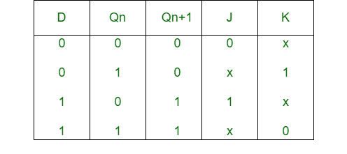
Step-2: Boolean Expression Derivation
Using the K-map, we find the boolean expression of J and K in terms of D and Qn.
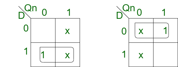
J = D
K = D'
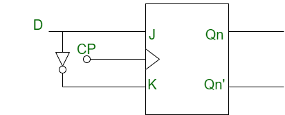
Step-3: Circuit Diagram Construction
We construct the circuit diagram for the conversion of a JK flip-flop into a D flip-flop.
Serial Input/Output Shift Registers Explained
Shift Registers:
Shift registers are digital circuits that store and shift data in a serial or parallel manner. Let’s explore the difference between Serial Input Serial Output (SISO) and Serial Input Parallel Output (SIPO) shift registers.
Serial Input Serial Output (SISO) Shift Register:
Circuit:
A SISO shift register consists of a series of flip-flops connected in a chain, with the output of one flip-flop connected to the input of the next.
Operation:
- Serial Input: Data is input serially, one bit at a time.
- Shifting: The data is shifted through the flip-flops on each clock pulse.
- Serial Output: The data is output serially, one bit at a time.
Serial Input Parallel Output (SIPO) Shift Register:
Circuit:
A SIPO shift register consists of a series of flip-flops connected in a chain, with the output of each flip-flop connected to a parallel output line.
Operation:
- Serial Input: Data is input serially, one bit at a time.
- Shifting: The data is shifted through the flip-flops on each clock pulse.
- Parallel Output: The data is output in parallel, with all bits available simultaneously.
Key Differences:
- Output Format: SISO outputs data serially, while SIPO outputs data in parallel.
- Output Availability: In SISO, data is available one bit at a time, while in SIPO, all bits are available simultaneously.
These shift registers have different applications, such as serial-to-serial data transmission (SISO) and serial-to-parallel data conversion (SIPO).

Design a 4-bit Up/Down Ripple Counter
(Note: The design details for a 4-bit Up/Down Ripple counter are not provided in the original document.)
Ring Counter vs. Johnson Counter Comparison
Ring Counter:
Circuit:
A ring counter consists of a series of flip-flops connected in a circular manner, with the output of the last flip-flop connected to the input of the first flip-flop.
Operation:
- Initial State: Only one flip-flop is set to 1, while the others are reset to 0.
- Clock Pulse: On each clock pulse, the 1 is shifted to the next flip-flop in the ring.
Johnson Counter:
Circuit:
A Johnson counter, also known as a twisted ring counter, is similar to a ring counter but with a twist. The output of the last flip-flop is inverted and connected to the input of the first flip-flop.
Operation:
- Initial State: All flip-flops are reset to 0.
- Clock Pulse: On each clock pulse, the data is shifted through the flip-flops, and the inverted output of the last flip-flop is fed back to the first flip-flop.
Key Differences:
- Feedback Connection: A ring counter has a direct feedback connection, while a Johnson counter has an inverted feedback connection.
- Sequence Length: A ring counter generates a sequence of length ‘n’ (number of flip-flops), while a Johnson counter generates a sequence of length ‘2n’.
- Output Pattern: A ring counter produces a straightforward shift pattern, while a Johnson counter produces a more complex pattern due to the inverted feedback.
These counters have different applications, such as frequency division, sequence generation, and digital control systems.
Key Digital Circuit Parameters Explained
Digital Circuit Parameters:
(a) Fan-In:
- Definition: Fan-in refers to the number of inputs a logic gate can handle.
- Importance: It determines the complexity of the gate and its ability to perform logical operations.
(b) Fan-Out:
- Definition: Fan-out refers to the number of inputs or gates that can be driven by the output of a logic gate.
- Importance: It determines the gate’s ability to drive multiple loads without significant degradation of the output signal.
(c) Noise Margin:
- Definition: Noise margin is the amount of noise that a digital circuit can tolerate without causing errors.
- Importance: It ensures reliable operation of digital circuits in noisy environments.
(d) Power Dissipation:
- Definition: Power dissipation refers to the amount of power consumed by a digital circuit.
- Importance: It affects the circuit’s energy efficiency, heat generation, and reliability.
(e) Propagation Delay:
- Definition: Propagation delay is the time it takes for a signal to propagate through a digital circuit.
- Importance: It affects the circuit’s speed, performance, and timing.